Following on from a customer query, we can confirm that one can install install addressable RGB LEDs/NeoPixels inside a 60 mm diameter arcade button. It’s not the easiest build, so whether one should attempt this is another matter entirely.
Thin (and I mean thin: I used 28 AWG) Silicone Cover Stranded-Core Wire in several colours. You’ll want to cut this quite long at first, as you have to ease it through some tiny holes in the button assembly. If you solder connectors on the end, you won’t be able to disassemble or install the button without cutting them off. Do I speak from experience here? You betcha!
The usual soldering/hot gluing/bending/prying/grabbing/cutting tools you already know and love. In addition, you might consider a non-marring spudger and a pair of arterial forceps (aka hemostats) or needle nose pliers too.
I’m not going to cover soldering the wires to the LED PCB in any depth here. You’ll need three wires: 5 V power, Ground and Data. Even though the LEDs I used need 5 V power, they are quite happy with 3.3 V logic on the data line. They need more than 3.3 V power to light, though.
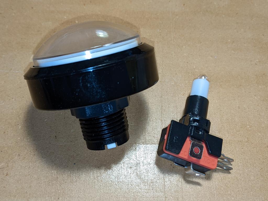
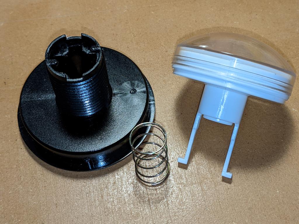
The button in two pieces, as you might expect to receive it
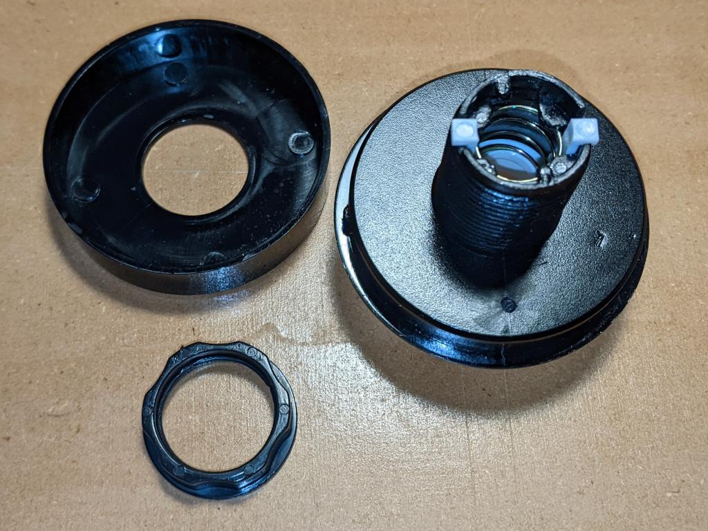
Main parts of the button top, once you’ve removed the lock ring
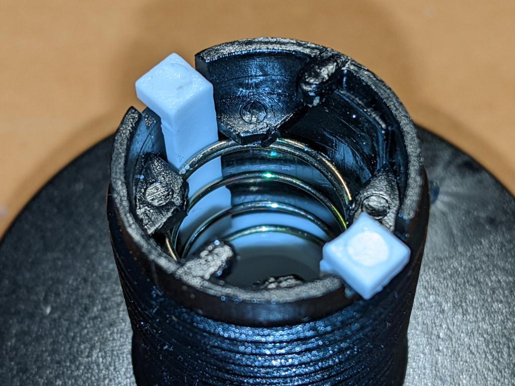
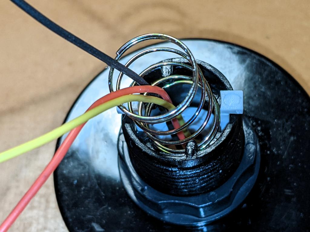
First step is to ease the spring out without bending it too much or breaking the retainer tabs
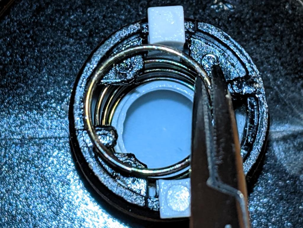
I used small forceps to ease the spring out. Once you get it started, it unscrews easily from behind the retainers
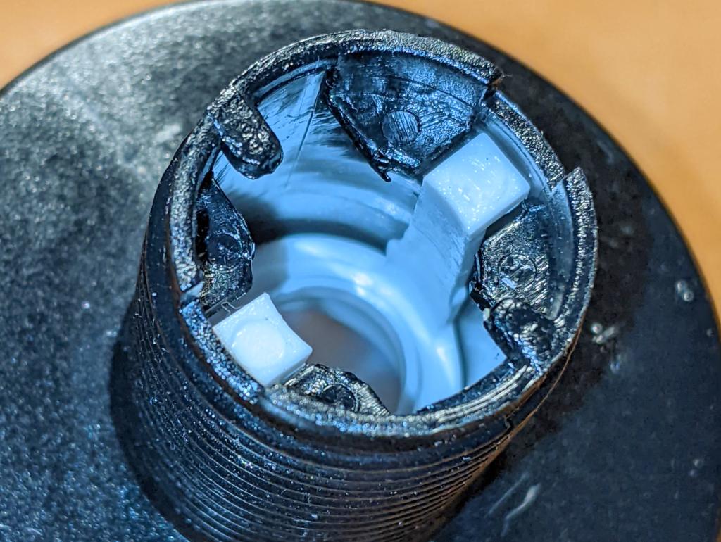
Now the spring is out the way, you can squeeze in the actuator tabs and push them down the shaft to liberate the button top
The button top disassembled
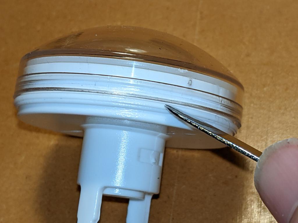
Carefully lever off the clear top with a blunt tool like a spudger. Now would have been a great time to clean dust and other wee bits off your workspace, as they’ll surely end up inside the button, looking nasty
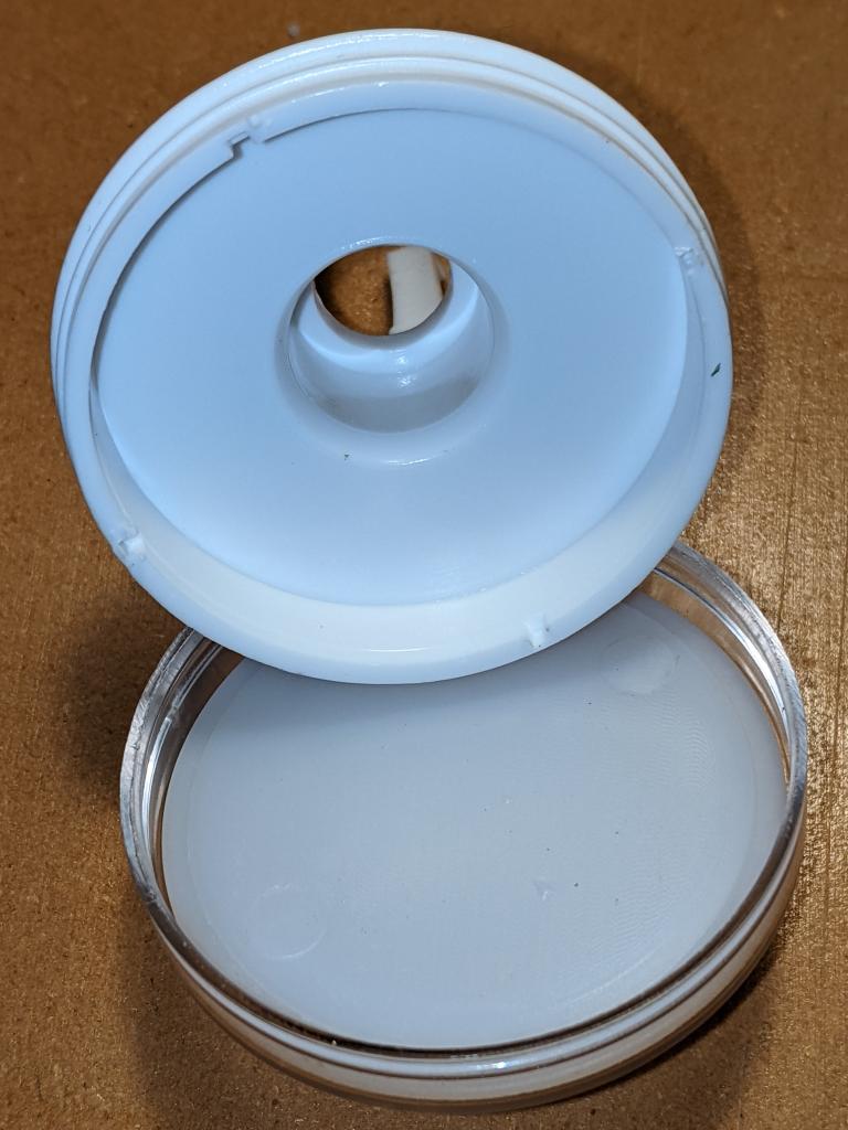
The button top opened up. The cavity is about 45 mm in diameter and only a few millimetres deep
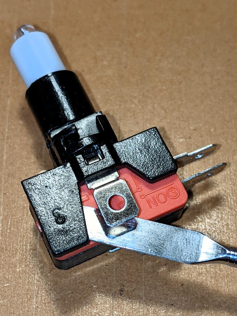
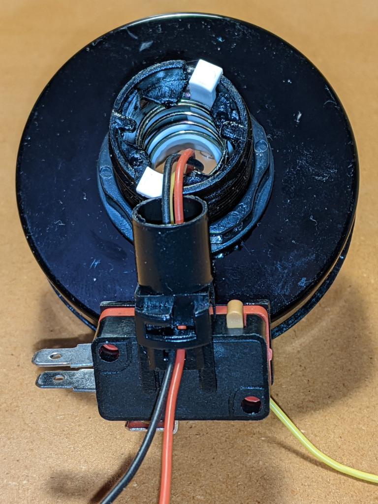
Removing the LED holder from the microswitch is done by levering open (gently) the plastic tab that clamps the holder onto the switch.
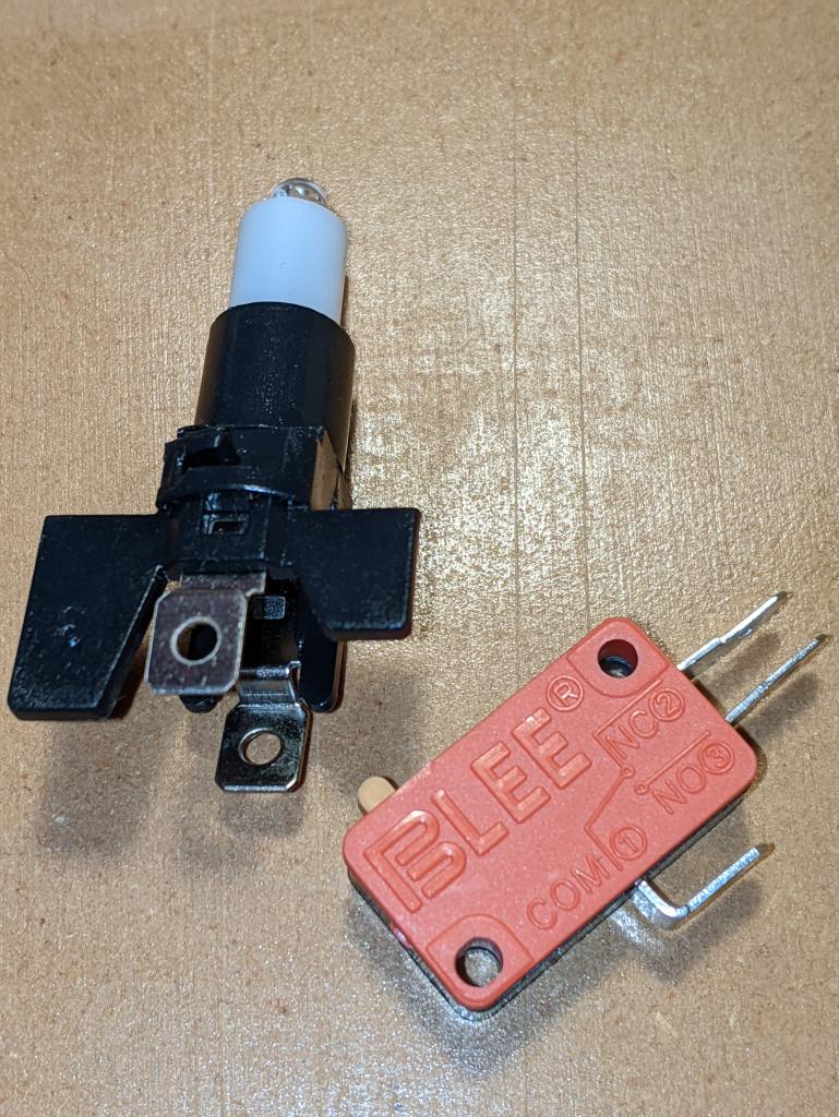
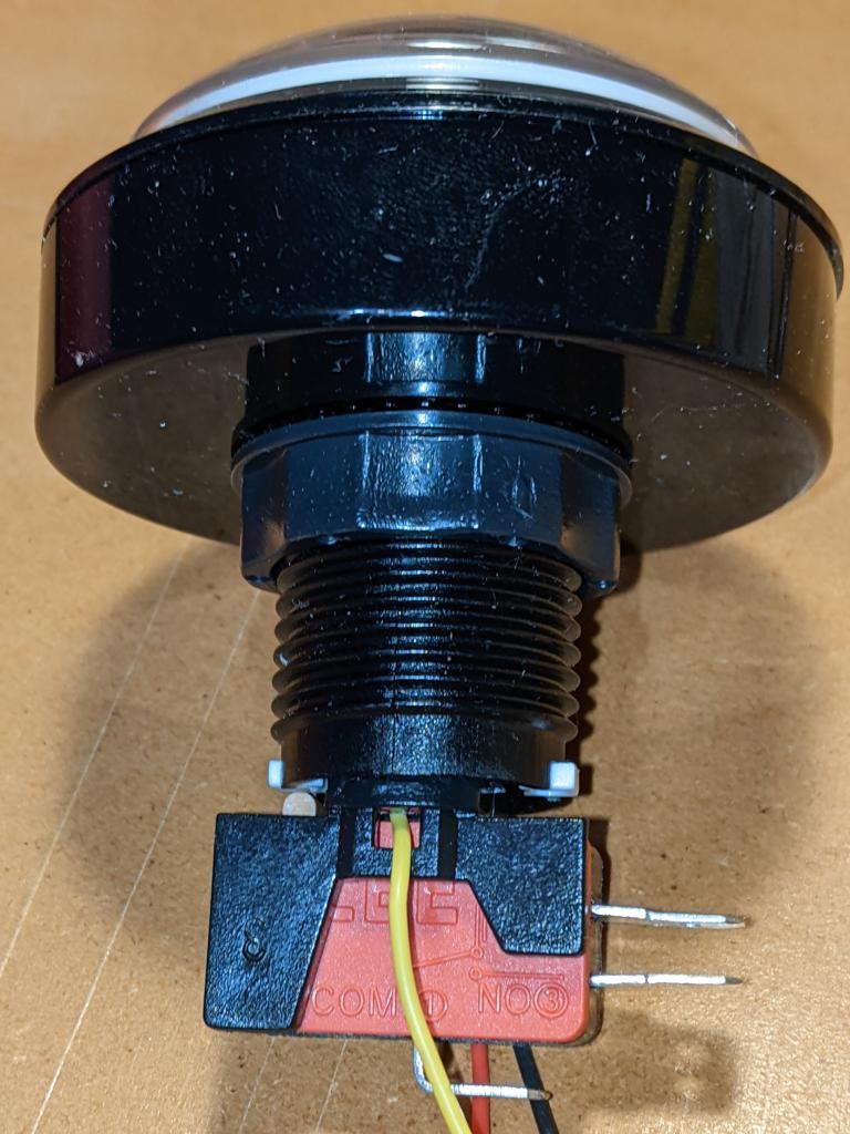
LED holder and microswitch separated. For normal button operation, the contacts NO and COM become connected when the button is pressed. The spade contacts on the LED holder look like they should come out, and they will (soon)
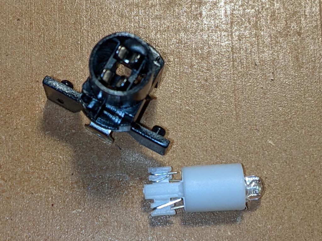
Pull the LED out from the holder, and you’ll see the metal clips that held it in place. These clips have to come out: I found the pushing them in slightly while pulling down on the spade connector eased them out eventually
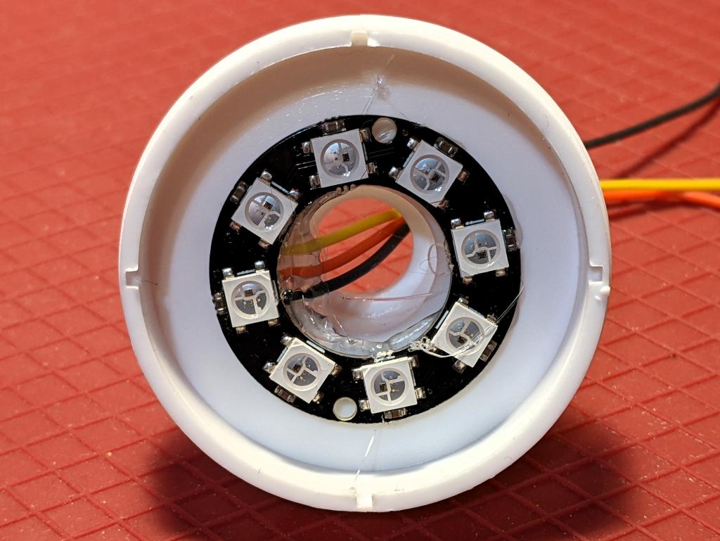
LED ring hot glued into place. Make sure that the wires are properly secured, as you don’t want to take this apart againFit the clear button top back inside the base, feeding the wires through the shaft. Fitting the return spring back in is a bit more chaotic than getting it out. I ended up jamming it in with forceps, and it seemed to sort out okay despite that
The really fiddly bit: feeding the wires through the tiny gaps where the LED holder clips/contacts used to be. Even using thin (28 AWG) silicone covered wire, all three wires couldn’t fit down one side. Make sure the wires are pulled gently through, and aren’t snagged anywhere
Finished! Make sure that the switch actuates properly by lining up the LED holder in the bayonets inside the shaft. Of course, you’ll have wanted to install the button in your project before doing this assembly, as you’ll have to feed those pesky wires back through again if you haven’t …